


Introduction
Part One of our article (Technical Talk 4) on alternative fuels in Switzerland during World War II was on the use of acetylene gas. In Part Two we cover the use of producer gas.
Producer gas had been of interest to the Swiss for many years before the war and was commonly derived from wood or charcoal. Other sources were anthracite or residual coke, but Switzerland’s lack of coal made these virtually non-existent. The wood used was mainly of Swiss origin, usually a combination of beech and fir; for steady gas production this needed to be well seasoned, with as low a water content as possible and a regular block size.
In 1943, the estimated number of vehicles in Switzerland running on producer gas was only 5,000 – thought to be a poor return on the extensive research work carried out to make its use possible.
Producer gas
Producer gas is a mixture of flammable gases (principally carbon monoxide and hydrogen) and non-flammable gases (mainly nitrogen and carbon dioxide) made by the partial combustion of carbonaceous substances (wood, coal or their derivatives) in an atmosphere of air and steam. The name came about because the gas was characteristically low in heating value but cheap to make, so that large amounts could be made and burned.
The reactions to create producer gas are generally exothermic and proceed as follows:
Formation of producer gas from air and carbon:
C + O2 → CO2, +97,600 calories
CO2 + C → 2CO, –38,800 calories
2C + O2 → 2CO, +58,800 calories
Reactions between steam and carbon:
H2O + C → H2 + CO, –28,800 calories
2H2O + C → 2H2 + CO2, –18,800 calories
Reaction between steam and carbon monoxide:
H2O + CO → CO2 + H2, +10,000 calories
CO2 + H2 → CO + H2O, –10,000 calories
Technical challenges
Wood gas producer equipment was cumbersome, because wood vinegar, acids and water had to be separated, requiring an elaborate filter system. A high carbonisation temperature was also required to crack the organic matter and thus to enable rapid starting with no loss of power from flat spots, but this high temperature caused considerable wear to the two key elements of the system: the tuyere and the furnace.
The most highly stressed part of the producer plant was the tuyere (B in Figure 1, a diagram of the Autark charcoal producer plant). This was a nozzle through which air was sucked into the furnace (the lower half of the hopper A in Figure 1) to maintain the incandescence of the fuel and thus the producer gas reaction. It should ideally have been made from chrome-nickel steel to give good thermal resistance, but lack of such alloys from the outbreak of war reduced the useful life of the tuyere from 100,000 miles to between 10,000 and 20,000 miles. A practical solution was to design an easily exchangeable, inexpensive carbon steel tuyere.

Figure 1. Diagram of the Autark charcoal gas plant.
Exhaust gas mixture control
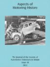
To compensate for the lower power output of producer gas, the compression ratio of converted petrol engines was raised to at least 8:1. This would make engines incapable of running on petrol. To make it possible to run on either fuel, exhaust gas mixers became popular. The “Surcarburex” equipment (see Figure 2) consisted of a small separate expansion chamber, a by-pass pipe and compensation chamber to dampen extreme pressure variations, and a mixture regulator mounted on the air inlet of the petrol carburettor. A three-way junction piece allowed instant changeover from producer gas to petrol.
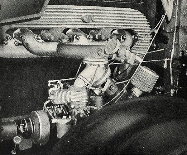
Figure 2. “Surcarburex” exhaust mixture control for operation on producer gas or petrol.
Exhaust turbo-driven blowers
The power loss on producer gas could only be partially be overcome by a raised compression ratio and the use of exhaust gas mixture control. However, pressure-charging the gas by means of an exhaust turbo-driven blower could restore power levels to those expected from petrol.
Charcoal producers
Much progress was made in the use of charcoal in producer plants for private cars. The producer had to allow for the rapidly varying extent of the oxidation zone that resulted from the frequently changing loads on a car engine. The best results were obtained by passing the air stream across the producer, as in the Autark, Royal and other “cross-draught” types. Figure 1 shows the air entering through the tuyere B on the left and exiting as producer gas through outlet D on the right.
Quite apart from the pressure-damping by-pass in an exhaust gas mixture control system, there was another by-pass – this time for cooling of the producer gas after the cyclone filter and before the cloth filter. Figure 1 shows this on the left: F is the vertical gas cooler, heavily finned, and G is the cooler by-pass valve. In Figure 3 is a Royal charcoal gas plant with four by-pass gas coolers between the hopper and furnace on the right and the filter assembly on the left, and Figure 4 shows a Riwa plant with a finned gas cooler between the hopper and furnace on the left and the filter assembly on the right.
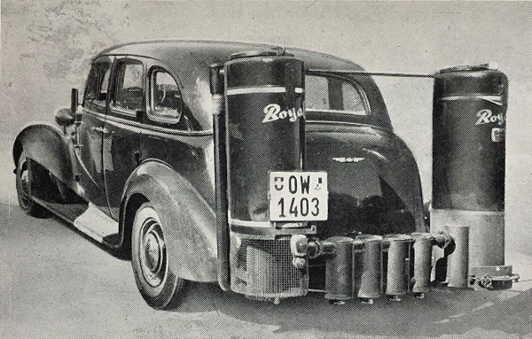
Figure 3. Royal charcoal gas plant with four by-pass gas coolers.
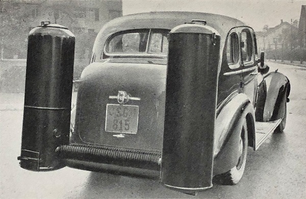
Figure 4. Riwa charcoal gas plant with a finned gas cooler.
The end of the tuyere near the fire zone was subjected to very high thermal stress, reaching at least 1,800 deg. C; enabling the tuyere to stand up to such a temperature required considerable innovation. There were air-cooled and water-cooled designs, and twin-walled constructions filled with low-melting-point metals such as sodium or lead. Bodies were made of copper or other good heat conductors, and the outer part of the nozzle was commonly finned.
Charcoal grain
To reduce hollow spaces in the charcoal hopper, and consequent flat spots in gas production, a fine grain of charcoal was used, below 3/8 in. diameter. The fuel therefore flowed almost like a high-viscosity fluid; it quickly became incandescent and produced high-quality gas within 30 seconds.
Filtering
Resistance to gas flow could become considerable at high gas speeds, and filtering of impurities was therefore vital. Large impurities were dealt with by a centrifugal cyclone filter (E in figure 1). Secondary filters were cloth, sisal or wood chippings soaked in oil, and the finest dust particles were separated out by oil filters. Figure 1 shows the filter on the right. It could be separate from the producer and therefore mounted at the front of the vehicle with the producer at the rear. In Figure 1 the filter is attached at its open mouth and supported on a wire filter support. It could easily be withdrawn from the filter body for cleaning.
Water injection
Gas quality could be improved by using the heat of the fire zone to produce water gas (a gas consisting only of the two flammable constituents carbon monoxide and hydrogen). A water injection system used a heat exchanger to vaporise an additional supply of water that was then led over the incandescent charcoal.
Gas-air mixers
A road transport engine has a constantly changing demand for gas. The mixing valve to regulate the gas-air mixture therefore needed to give the minimum resistance to the gas stream under all conditions. Although producer gas was initially thought to be suitable only for larger capacity engines, developments in these valves enabled producer gas to be used for engines as small as 1,000 cc.
External appearance
The external form of producer gas generators did improve, but never achieved the elegance of some acetylene systems. The hopper could be circular or rectangular in section, but the incandescent reduction zone had to be circular to prevent thermal tension at corners. Twin walls were sometimes fitted for the sake of appearance, with the outer one being cellulosed to match the car’s coachwork and even decorated with chromium-plated strips. Figure 5 shows a Carbonia charcoal gas producer with a central furnace flanked by two double-walled filters, all clearly painted in the car’s main body colour and looking almost (but not quite) as stylish as a post-war American continental kit.
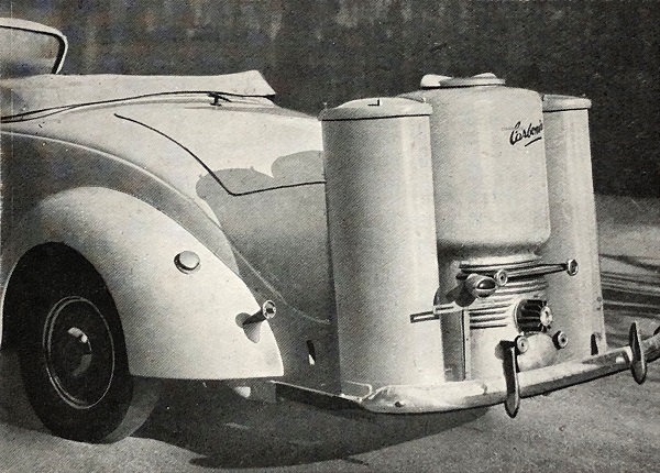
Figure 5. Carbonia charcoal gas producer with two double-walled filters.
The Royal gas plant in Figure 6 is less well styled, but at least the white lining stripes have made an attempt to improve the appearance of the gas producer.
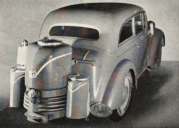
Figure 6. Stylised Royal charcoal gas plant.
Front mounting of the plant was often preferred, to keep it clear of access to the luggage compartment. The Riwa plant in Figure 7 is entirely front mounted, with two horizontal filters fitted with leather winter covers. The front mounting enabled the tuyere to be air-cooled, and it can be seen low down at the front of the furnace.
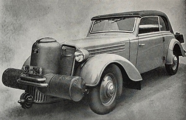
Figure 7. Riwa front-mounted charcoal grain plant.
Figure 1 displayed an Autark plant diagrammatically, and Figure 8 shows it installed in a car. The two pictures illustrate how the plant can be at the rear of the car and the main filter can be at the front. In the left-hand image the finned gas cooler is on the left of the producer and the cyclone filter on its right. The right-hand image shows the front-mounted main filter. It is horizontally mounted, double-walled and painted in the car’s body colour with an embellishing chrome strip across the front – all in an attempt to improve its appearance.
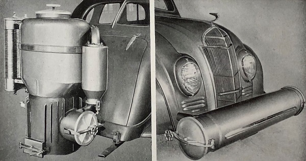
Figure 8. On the left, the Autark charcoal gas producer with cyclone filter and gas cooler. On the right, the Autark double-walled filter unit mounted on the front of the car.
The appearance of wood gas producers suffered from their much greater bulk and the need to cool the gas from the high carbonisation temperatures required for wood. In Figure 9 is a Kaiser wood gas producer with duplicated gas coolers.
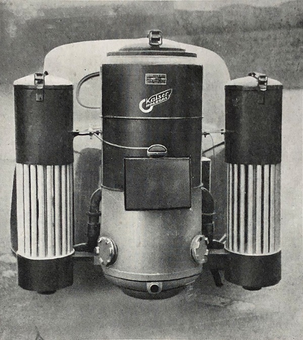
Figure 9. Kaiser wood gas producer with duplicated gas coolers.
Performance
Producer gas had inherently low calorific value, and a modern light petrol engine with a compression ratio of 6:1, operating at 4,000 rpm, could be expected to develop only 50 per cent of the power of the same engine running on petrol. The power peak was at a much lower engine speed and the power curve fell off rapidly. Torque was also reduced, and therefore acceleration. Maximum speeds were limited to around 60 mph, not least because of the air resistance of the producer plants. The engine always had to be kept running at a relatively high speed to maintain suction through the tuyere and ensure regular production of gas. The driving range varied between 60 and 200 miles, depending on hopper capacity and engine size. Consumption equivalent to one gallon of petrol was approximately 24 to 28 lb. of wood, 13 to 18 lb. of charcoal or 11 to 14 lb. of charcoal grain.
Maintenance
As designs improved, maintenance work gradually became less onerous, but it was still necessary to clean filters every 500 miles, remove ash every 1,000 miles and clean the producer fully every 2,000 miles. Neglect of filters, however, could allow impurities to enter the engine and cause rapid wear. Engine overhauls were needed at half the usual mileages due to the relatively dry combustion process.
Another curious postscript
Producer gas systems were awkward and bulky – even more so than those used for acetylene. But, as with acetylene in Technical Talk 4, Figure 10 shows that it was possible to run a motorcycle on this gas – except that now it required a sidecar to accommodate the equipment.
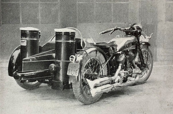
Figure 10. Motorcycle and sidecar outfit equipped with a charcoal gas plant.
Drawings and photographs courtesy of the Richard Roberts Archive
Leave a Comment