


The origins of the opposed-piston two-stroke engine can be traced back to 1898, when an Oechelhäuser gas-powered engine of this type, with horizontal layout and producing 600 hp, was installed at the Hoerde ironworks. This design was also produced under licence by Deutsche Kraftgas Gesellschaft in Germany and William Beardmore & Sons Ltd in Britain.
Compared to contemporary two-stroke engines which used one piston per cylinder, the two main advantages of the opposed-piston engine were elimination of the cylinder head and valvetrain, thus reducing weight, complexity, cost, heat loss and friction loss, and the uniflow-scavenged movement of gas through the combustion chamber, which avoided the drawbacks of contemporary crossflow-scavenged designs.
Among the most successful diesel engines of this type were those developed by Junkers from the original horizontal installations to the vertical layout we see here. Although their Jumo 205 aero engine of the early 1930s is their best known, Junkers developed this type for automobile use during the late 1920s.
Two-stroke engines normally suffer from poor volumetric efficiency because inlet and exhaust ports open and close at the same time and are generally located across from each other in the cylinder. This leads to poor scavenging of the burnt charge, which is why valve-less two-strokes generally produce smoke and are inefficient.
Junkers solved this problem through clever arrangement of the ports. The intake port was at one end of the cylinder and the exhaust at the other, creating uniflow (one-directional) scavenging. In the automobile application, air was scavenged from the atmosphere at the top of the engine. It was forced into the space between the two pistons by a scavenge pump. The scavenge pump plunger was attached to the top of the top piston, sliding in a casing integral with the cylinder head.
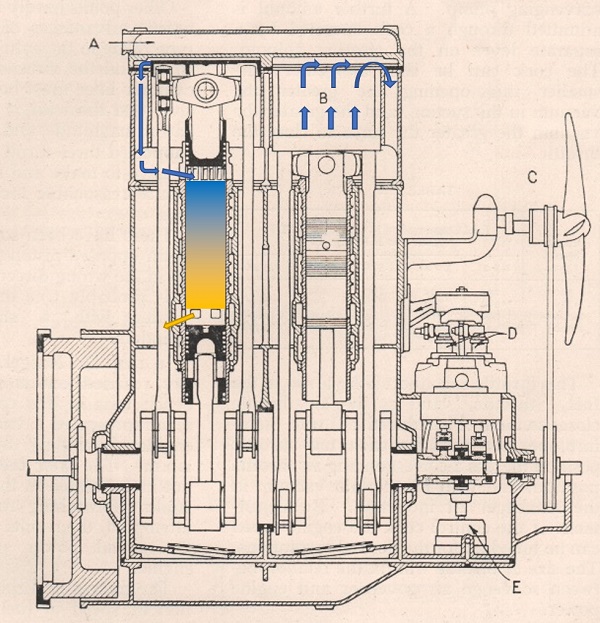
Figure 1
Figure 1 above shows a two-cylinder, four-piston version of the engine. Each of its two cylinders has three cranks, with no intermediate bearings. The centre crank is attached to the lower piston, and the two outer cranks are attached to the top piston by two side rods.
The colours in our figure show the flow of gases. At this point in the cycle the right-hand pistons are together. The air between them is compressed, ready for injection of fuel oil between the pistons that will combust and cause the explosion stroke that forces them apart.
But another operation is also taking place. A simple spring-loaded one-way valve has allowed air to flow into the scavenge-pump space B above the right-hand piston on its previous downstroke. The right-hand blue arrows show how the scavenge pump will push the air into the cylinder as it goes upwards on its explosion stroke.
The left-hand pistons are apart. The explosion stroke has forced the air in the scavenge space upwards – but the spring-loaded valve is now closed, forcing the air to turn downwards into the combustion space between the pistons, through ports in the cylinder wall. The left-hand blue arrows, and the blue inlet air, show that flow. The spent exhaust gases (yellow) are forced downwards by the incoming air, through the exhaust ports. The yellow arrow shows that flow.
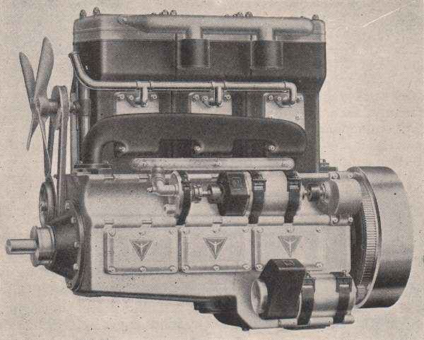
Figure 2
Figure 2 above shows a three-cylinder, six-piston version of the engine. From top to bottom of the main block can be seen the air inlets, the fuel supply to the injectors and the exhaust manifold.

Figure 3
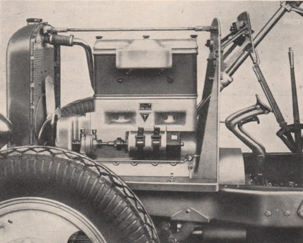
Although these were experimental engines, figure 3 above at least proves that a two-cylinder version was installed in a car – but we have found no evidence to indicate the chassis used.
The Junkers engine was a great success in aircraft such as the Junkers Ju 86P and -R high-altitude reconnaissance aircraft, and the 46-metre wingspan, six-engined Blohm & Voss BV 222 Wiking flying boat. In all more than 900 of these engines were produced, in the 1930s and through most of World War II.
Drawings and photographs courtesy of the Richard Roberts Archive
I am reminded of John Wright’s splendid ‘special’ powered by a Commer TS3 engine which follows similar principles.
But with its supercharger, it not only goes well and looks ‘right’, but also makes that splendid noise. The chassis is Leyland, hence the radiator badge.
See
https://www.jalopyjournal.com/forum/threads/specials.720448/page-4
Scroll down to Ned Ludd.
Video with sound here:
https://trshow.info/watch/OTmkO6D0OWI/leyland-sports-car-with-commer-ts3-tilling-stevens-engine.html
Because two stroke engines do not have an intake stroke there has to be another way to get air into such an engine, normall by mechanical means — scavage blower.
If such blowers are taken off a two stroke Diesel and fitted to a four stroke engine then you can force air into the engine – supercharging.