


Introduction
The Model T Ford is rightly celebrated as the first affordable motor car and, from 1913, an example of the cost advantages of the moving assembly-line system.
Its engineering design was in some respects conventional but in others unique – as will be seen from this description, based on information from its launch in October 1908 and subsequent developments from the car’s later history.
Our particular thanks are due to Neil Tuckett of Tuckett Brothers for his considerable help in reviewing an early draft, and in providing and explaining to us later images that make clear the significant improvements made to the Model T after its initial 1908 launch.
The engine – a single casting and a clean layout
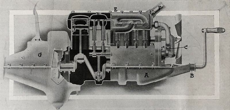
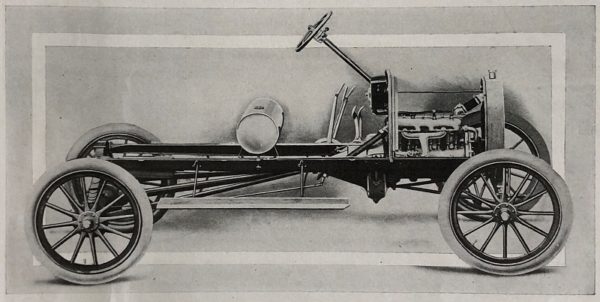
Fig. 1 – The engine of the 1908 Model T
Fig. 1 shows the original 1908 Ford Model T engine. The first innovation in the front-mounted 177-cubic-inch (2.9-litre) inline four-cylinder engine was the casting of the cylinders and upper crankcase in a single piece, at a time when most manufacturers mounted separate cylinders or multiple groups onto a base crankcase. The lower half of the crankcase was a stamped casing A, which extended rearwards to form the lower half of the casing for both the flywheel and the transmission. The upper half of the transmission case G also enclosed the top half of the flywheel.
This was not the only novelty: there was a separate one-piece water-jacketed head casting E for all four cylinders. The advantage of such a separate cylinder head lay in simplicity of machining: it did away with the intricate coreways of a fixed-head cylinder block and allowed passages and cylinder bores to be machined and reamed with great ease.
The inlet and exhaust valves and carburettor were all on the right-hand side of the engine with nothing on the left. The whole arrangement gave a very clean external appearance. Further simplification came from siting the oiler and magneto in the flywheel and from the simplified water piping consisting only of a short pipe from the pump C to the front end of the water jacket and a short return pipe F from the cylinder head to the vertical-tube radiator.
Engine development

Fig. 2 – The engine of the 1919 Model T
Fig. 2 shows the many changes that were made to the original 1908 engine. The image is from 1919 but by 1911 virtually all these changes had been completed.
Firstly, the water cooling. The first 2,447 units were cooled with water pumps, but virtually all later cars used the simpler thermosyphon principle. The water pump in Fig. 1 behind the engine fan is therefore clearly missing from Fig. 2.
The transmission case was considerably modified, the original horizontal square cover being replaced by a sloping cover on a much simpler casing. An even more extensive change was made to the sump. In Fig. 1 it is obvious that the entire sump had to be removed to access the main bearings. Fig. 2, however, shows a flat base to the sump, and just visible are the nuts that attach a bottom plate that allowed the bearings to be inspected.
Finally, Fig. 1 shows that the side-valves and springs were originally open to the elements; lubrication was total loss. Fig. 2 shows the forward cover plate of two that enclosed the valves and their springs, thus allowing lubrication by the oil circulating within the engine.
An inventive magneto
Unlike the expensive high-voltage ignition magnetos used on some other cars, the Model T used a low-voltage magneto incorporated in the flywheel, supplying alternating current to trembler coils to fire the spark plugs. The launch report listed the many parts that were NOT required: brushes, contact points, moving contact, moving wires, gearing, and “the many other parts associated with different types of magnetos.” Next to the engine were sixteen stationary coil windings. Rotating with the flywheel were sixteen V-shaped magnets distributed around the periphery of the flywheel with their apex towards the centre, “giving the appearance of a coarse-tooth circular saw.” The polarity of the coil windings alternated right and left; rotation of the magnets with the flywheel therefore set up an alternating current in the windings.
Fig. 3 shows the coils and magnets. The image is taken from a much later (1923) Ford Manual, but the arrangement had not changed.
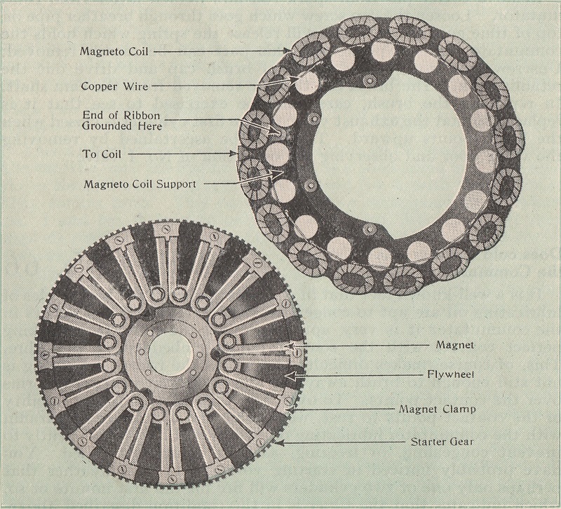
Fig. 3 – The stationary coils (above right) and rotating magnets (below left) of the magneto
The ignition system

Fig. 4 – The ignition system, with wire from the magneto, trembler coils in the dashboard-mounted box, commutator on the front of the camshaft, and spark plugs
Fig. 4 shows the ignition system that powered the spark plugs. The image is from 1919, but the principles had not changed from the very first cars of 1908. There are, however, two 1919 features: electric lighting, and the inspection covers over the side-valves and their valve springs.
The low-voltage AC current passed from the magneto to the wooden box on the dashboard that contained four trembler coils. All the trembler coils were therefore powered at one end but were only earthed at the right time by a commutator, or timer, driven from the front of the camshaft (and therefore running at half engine speed, to give each plug a spark every two engine revolutions). As soon as each trembler coil was earthed by the commutator it would create a high voltage that then passed to its spark plug.
This system was closer to that used for stationary gas engines than the expensive high-voltage ignition magnetos that were used on some other cars. Trembler coils produce a string of high-voltage sparks while linked by the commutator to the low-voltage magneto; this made the Model T more flexible as to the quality or type of fuel it used. The system did not need a starting battery, since hand-cranking would generate enough current for starting. Electric lighting powered by the magneto was adopted in 1915, replacing acetylene gas flame lamp and oil lamps, but electric starting was not offered until 1919.
Splash lubrication
As well as containing the magneto (as already described) and the planetary gearset (of which more later), the flywheel also acted as a lubricator: it splashed oil by centrifugal action into a pocket on the partition between the flywheel and the crankcase; from there the oil was led through a slanting duct to the front end of the crankcase to feed the splash system. The angle of this tube ensured that lubricant would still flow to the front of the engine when the car was climbing a 23 per cent slope.
Within the engine, the lower ends of the connecting rods dipped into the oil in the sump and distributed it to the cylinder walls, crankshaft bearings and upper and lower connecting rod bearings. The same oil was used for both engine and transmission and was replenished through an opening on top of the transmission case.
Suspension
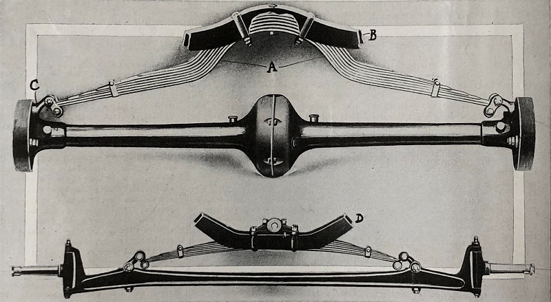
Fig. 5 – The original front and rear suspension using transverse leaf springs. Note the early deep-drawn form of the two halves of the axle housing
Model T suspension was by transverse semi-elliptical springs for both front and rear beam axles, as shown in Fig. 5. This allowed substantial wheel movement to cope with the rutted dirt roads of the time. The front axle was drop forged as a single piece of vanadium steel. Ford twisted many axles through eight full rotations (2880 degrees) and sent them to dealers to be put on display to demonstrate the superiority of this material.
Fig. 5 also shows the very early construction of the rear axle; each half was made from a single deep-drawn piece.
The differential
The original 1908 differential had white-metal bearings, as shown in Fig. 6: H for the pinion and K for the inner bearings of the half-shafts.
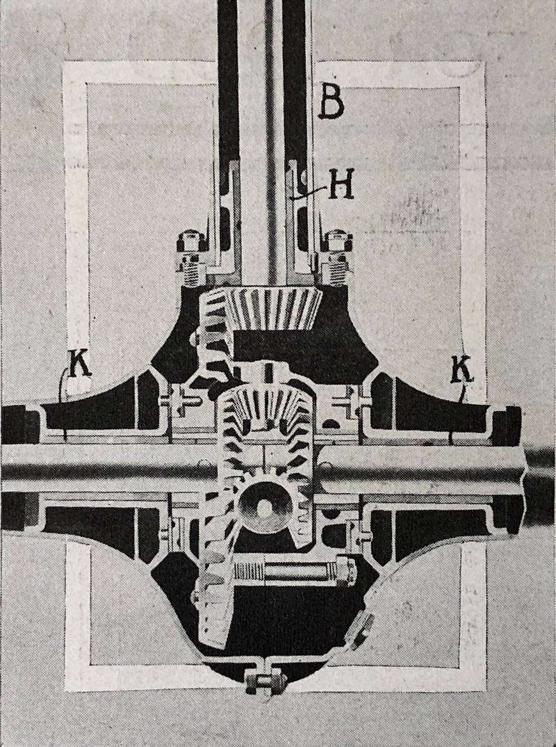
Fig. 6 – The original 1908 differential
Development of the rear axle and differential
The decision in 1908 to use deep-drawn rear axle casings for the Model T was curious: the earlier Model N had already used a more practical combination of cast differential housings and simple parallel axle tubes – and the Model T adopted this solution at some time before World War I. At the same time, Ford replaced the less satisfactory white-metal bearings with far more durable Hyatt roller bearings.
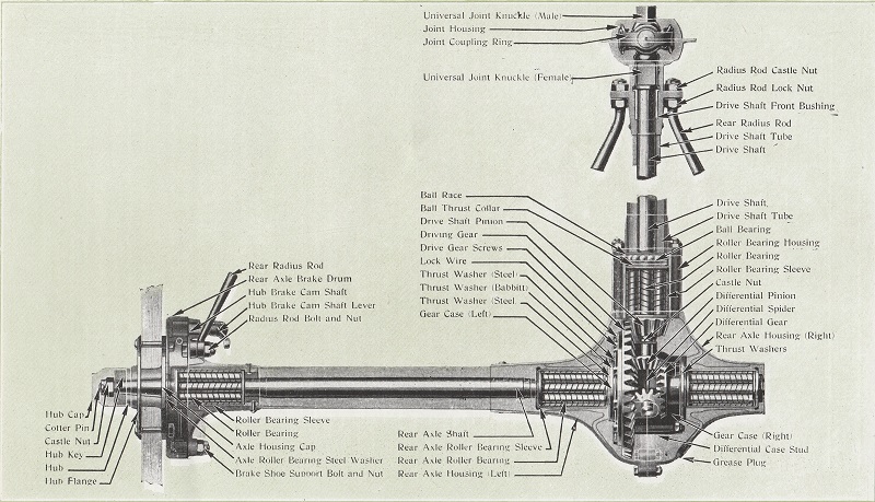
Fig. 7 – The modified rear axle, with cast differential housing, simple parallel axle tubes and Hyatt roller bearings
All the modifications to the rear axle can be seen in the sectional view in Fig. 7: the cast differential housings, simple parallel axle tubes, and Hyatt roller bearings on the pinion and on the inner and outer ends of the half-shafts. Fig. 7 also shows the helical grooves on the Hyatt rollers; these grooves alternated right and left, thus moving lubricant to and fro across the bearing but keeping it within the housing, for minimum leakage.
The Model T gearbox
The Model T Ford gearbox used a planetary transmission; this was completely unlike epicyclic units such as those under the Wilson patents. Its unique design was responsible for the curious combination of levers and pedals that initiated forward or reverse motion. The design has been attributed to Joseph A. Galamb, a Hungarian engineer employed by Ford from 1905 – but it is likely that the gearbox was the brainchild of a group of talented engineers assembled by Henry Ford, including Childe Harold Wills (later to design his own car, the Wills Sainte Claire), Joseph A. Galamb, Eugene Farkas, Henry Love, C. J. Smith, Gus Degner and Peter E. Martin. Other sources suggest that two further men were involved: Jules Hartenberger and Charles Balough. The design team of Galamb, Farkas, Balough and Haltenberger were all Hungarian immigrants who frequently discussed the project in their home language.
A paper published in 2008 gives some more insight into the origins of the gearbox. This was A Technical Examination of the Planetary Transmission of the Ford Model T by György Gyurecz, Adjunct Professor, Institute of Machine Design and Safety Techniques, Budapest Tech, Budapest, Hungary, and Dr. Trent E. Boggess, PhD, Professor of Economics, Department of Business, Plymouth State University, Plymouth, NH, USA. To quote the paper:
“The three Ford cars that immediately preceded the Model T were the N, R and S models. All three used the exact same [planetary] transmission, and there were two faults common to this transmission. First, since the transmission was in the open behind the motor the dust, dirt and grime that characterized early American roads easily reached the transmission and stuck to it because of the lubricant that had leaked out from inside the rotating drums. This created a condition in which the transmission parts would wear rapidly. The second fault was the difficulty associated with replenishing the lubricant inside the drums … lubrication must be forced into the transmission drums through two small slotted-head brass screws in the transmission drum and the transmission output shaft. These are difficult to reach when the engine and transmission are at room temperatures, but become almost impossible to reach when the engine and transmission are hot after having just completed a run. The result was that these transmissions usually did not receive enough lubrication to prevent excessive wear on the internal parts. It appears today that more Model N, R and S cars died from a lack of transmission lubrication than from any other cause.
“In January or February of 1908 Henry Ford asked Joseph Galamb and Charles Balough to set up their drawing boards and a blackboard in the northeast corner of Ford’s Piquette Avenue factory. This factory was only 3 years old and it stands on the corners of Piquette Avenue and Beaubien Street in what at the time was the northern outskirts of Detroit. Both men were trained at the Royal Technical Institute in Budapest. The experimental room where the Model T was designed was located on the 3rd floor of the northeast corner of the factory building. Charles Balough indicated in his reminiscences that while ‘Mr. Ford was not enthusiastic about a sliding gear transmission, he wanted to experiment with it on the Model T.’ After completion, the car was tested on the public streets near the Ford factory. The factory area was served by streetcars which transported the workers to the factory in the morning and back home at night. The test was conducted late in the day and an accident occurred that destroyed the car. Mr. Balough thought Mr. Ford would fire him on the spot for wrecking the car, but Mr. Ford surprised him by saying ‘Charley, that’s the best job you ever did for this company’. It marked the end of the sliding gear transmission experiments and the focus on developing a better planetary transmission.
“Joseph Galamb claims credit for most of the design work on the Model T’s transmission. This design began soon after Mr. Ford had assigned him to Piquette’s 3rd floor experimental room. The project took 5 or 6 months to complete. The transmission was first drawn on a blackboard. On the blackboard Mr. Ford could follow Galamb’s design very closely, making any changes he did not like. Galamb determined the gear ratios and the unique design that combined the transmission and the flywheel so that the transmission rotated with and effectively became part of the flywheel. Mr. Ford wanted to keep the car as light as possible, and this design saved the weight of a separate casing or frame to hold the three planetary pinion gears.
“When the drawing of the transmission was completed, Mr. Ford instructed Galamb to have a small brass model made. The gears and the drums were all made from brass, and the design could be tested by holding one of the drums between their fingers to make the transmission go into low, reverse or brake. ‘He [Mr. Ford] liked to see a model working first. He didn’t like to go just by the blueprint. He never did. He always liked to have a sample made first’ [Reminiscences of Joseph Galamb].
“The next innovation in the design of the transmission was coupling it directly to the engine’s crankshaft then enclosing the engine transmission in an oil-tight, dust-proof case. The case consisted of a cover over the top and the oil pan on the bottom. This design eliminated two of the major faults with the earlier Ford planetary transmission. First, the case kept the dust, dirt and road grime out of the transmission. Second, the transmission was constantly lubricated by the same oil as the engine. Adding oil to the engine added oil to the transmission at the same time.
“The final design proved to be very reliable and durable. It was used on all of the 16 million Model Ts [sic: in fact nearer to 15 million] produced worldwide from 1908 to 1927.”
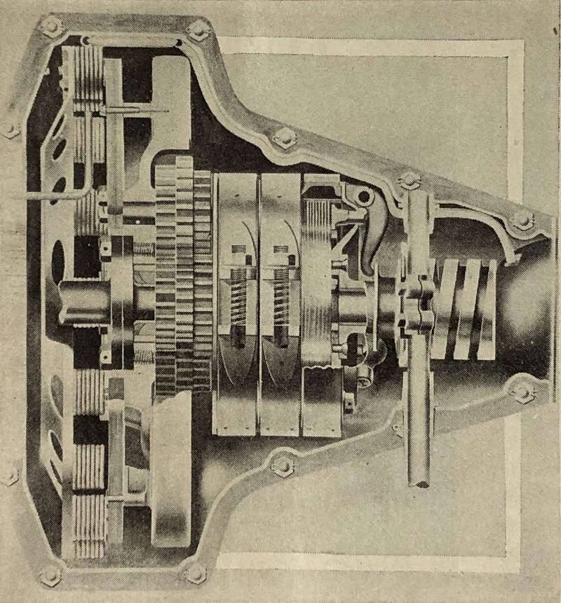
Fig. 8 – The Model T gearbox
The illustration in Fig. 8, from October 1908, gives some idea of the operation of the gearbox: planetary gears on the left are braked by three external bands acting on drums attached to the gears to give two forward speeds, reverse, and a transmission brake. All the gears, drums and brake bands run in oil.
Pedals and levers – the first 800 cars
Fig. 9 shows the arrangement of pedals and levers in the first 800 Model T Fords. The brake pedal 1 is on the right and the clutch/low gear pedal 2 on the left. Lever 3 operates reverse, and lever 4 is the handbrake.
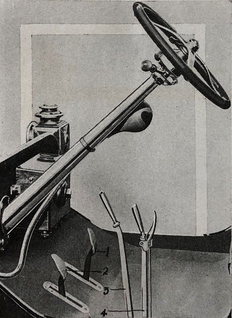
Fig. 9 – The controls on the first 800 cars
Pedals and levers – all further cars

Fig. 10 – The controls on all further cars
In all cars after the first 800, the 3 brake bands and clutch were operated by three pedals and a single handbrake lever, as shown in Fig. 10.
Pedals, handbrake and linkages
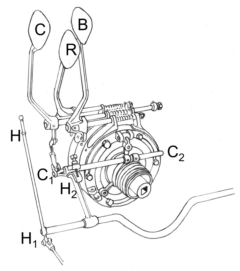
Fig. 11 – Pedals, handbrake and linkages
Fig. 11 gives more detail of the linkages between the pedals and handbrake and the internals of the gearbox. From left to right on the toe-board of the car the pedals are:
Left: C – Clutch and low gear pedal
Middle: R – Reverse pedal
Right: B – Transmission brake pedal.
The middle reverse pedal R sits proud of the other two pedals, to allow the driver to engage reverse without touching the clutch or brake pedals.
The handbrake H sits to the left of the driver. When pulled fully backwards, this operates the drum brakes on the rear wheels, through the rod H1.
How the gearbox works
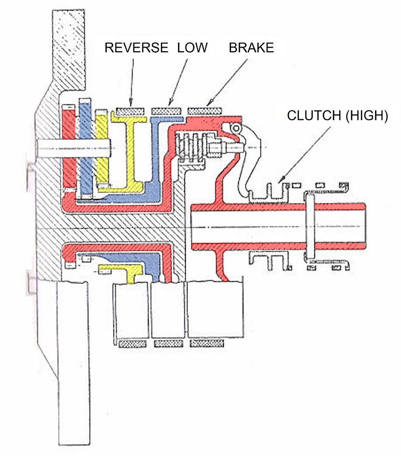
Fig. 12 – How the Model T gearbox works
Fig. 12 gives a more detailed view of the operation of the Model T gearbox.
Three sets of triple planet gears (red, yellow and blue in the diagram) are arranged at 120 degrees to each other and rotate upon three shafts attached to the flywheel. In the original design the three planet gears were riveted together; later, all three gears were machined from a single forging. The triple planet gears engage with three sun gears (also red, yellow and blue), which drive three concentric shafts that lead to the following:
Red: to the transmission brake band and then on to the output shaft
Blue: to the low-speed band
Yellow: to the reverse band.
Finally, there is a clutch mechanism inside the ‘red’ drum. Multiple clutch discs (a total of 25) are attached alternately to the inside of the drum and the outside of the extension of the shaft protruding from the flywheel (crosshatched in grey). Therefore, in the clutch’s resting position, the spring on the output shaft (visible in Fig. 12 as three rectangles above and three below the shaft) keeps the clutch discs engaged, and directly connects the flywheel, and thus the engine, to the entire ‘red’ output shaft. This gives 1:1 direct drive, or ‘high gear’.
The operation of the gearbox is as follows:
Low gear
The left clutch/low gear pedal C is pressed fully forward. This brakes the middle drum (blue in Fig. 12), which causes the combination of ‘blue’ and ‘red’ sun and planet gears to rotate to give low gear (the calculation of ratios will be seen later). The clutch is also disengaged by a series of levers C1 attached to the clutch pedal. These rotate the clutch yoke shaft C2 forwards. An arm hanging down from the middle of this shaft therefore pulls the clutch sleeve backwards, against the pressure of the spring, and disengages the clutch. This therefore separates the flywheel from the ‘red’ output shaft and only allows drive to pass through the ‘blue’ and ‘red’ gears.
Reverse
The middle reverse pedal R is pressed fully forward. This brakes the front drum (yellow in Fig. 12), which causes the combination of ‘yellow’ and ‘red’ sun and planet gears to rotate to give reverse gear (again, the calculation of ratios will be seen later).
The clutch also needs to be disengaged to separate the flywheel from the ‘red’ output shaft and only allow drive to pass through the ‘yellow’ and ‘red’ gears. For reverse, the clutch can be disengaged in one of two ways:
The first: The left-hand clutch/low gear pedal C is pressed only half-way down at the same time as the reverse pedal R is fully pressed. This disengages the clutch without braking the low-gear band. However, this has to be judged carefully to avoid the low-gear band slipping against the low-gear drum and thus heating up and causing excessive wear to the low-gear brake band.
The second: The handbrake H is moved to its centre position. The rod H1 is not pulled far enough to apply the brakes on the rear axle, but the curved ramp H2 is moved enough to rotate the clutch yoke shaft C2 forwards and disengage the clutch.
High gear
To move from low to high gear, the driver pushes the handbrake lever H fully forward and releases the clutch/low gear pedal C; both operations ensure that the clutch engages. Now the flywheel, and thus the engine, is directly connected to the entire ‘red’ output shaft. This gives 1:1 direct drive, or ‘high gear’.
Stopping the car
To stop the car, the driver presses the right-hand brake pedal B to operate the transmission brake. This brakes the entire ‘red’ output shaft. At the same time the handbrake must be pulled into its centre position to disengage the clutch; otherwise, the engine will stall. The brake pedal B can only be used intermittently, since constant application will heat up and wear out the transmission brake band.
On all cars up to 1925 the handbrake was only intended as a parking brake, operating cast iron shoes within steel drums. However, in an emergency it could be pulled back to operate the rear axle brakes to stop the car. For 1926 Ford increased the size of the rear drums and added a replaceable lining to the brake shoes, but never linked these brakes to the brake pedal. The new system was still only intended as a parking brake.
Braking improvements have been made over the years, including the after-market Rocky Mountain brakes, which are operated by the brake pedal and work external contracting bands on the existing rear brake drums.
Gear ratios
The low and reverse ratios are created by the different numbers of teeth on the sun and planet gears when the sun gears are braked by the relevant bands. The teeth numbers are given below:
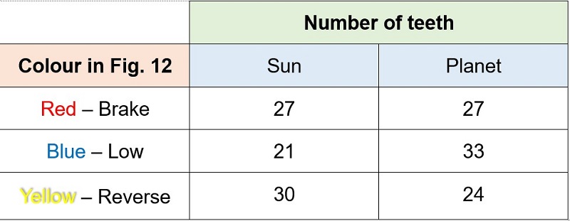
Gear ratio – low gear
When the ‘low’ band brakes the ‘blue’ sun gear, this forces the ‘blue’ planet gear to rotate backwards around the stationary sun gear. Because the planet is bigger than the sun (33 vs. 21) it rotates backwards at 21/33 of flywheel speed. The resultant speed is therefore +1 (forwards) – 21/33 (backwards). Because the ‘red’ and ‘blue’ planet gears are locked together, the ‘red’ planet gear rotates in the same way – but because the planet is equal in size to the sun (27 as well as 27) it will drive the output shaft forward at the same speed: +1 – 21/33 = +1 – 0.6364 = +0.3636.
The low gear ratio is therefore input speed/output speed = +1/+0.3636 = +2.75:1.
Gear ratio – reverse gear
When the ‘reverse’ band brakes the ‘yellow’ sun gear, this forces the ‘yellow’ planet gear to rotate backwards around the stationary sun gear. Because the planet is smaller than the sun (24 vs. 30) it rotates backwards at 30/24 of flywheel speed. The resultant speed is therefore +1 (forwards) – 30/24 (backwards), i.e. in reverse. Because the ‘red’ and ‘yellow’ planet gears are locked together, the ‘red’ planet gear rotates in the same way – but because the planet is equal in size to the sun (27 as well as 27) it will drive the output shaft at the same speed: +1 – 30/24 = +1 – 1.25 =
–0.25.
The gear ratio is therefore input speed/output speed = +1/–0.25 = –4:1.
The rear axle gear ratio
The Model T rear axle’s differential contained a pinion wheel with 11 teeth and a crown wheel with 40 teeth, thus giving a final drive ratio of 40/11 = 3.6363:1.
The overall ratios were therefore:
Low: 2.75 x 3.6363 = 10:1
Reverse: –4 x 3.6363 = –14.5452:1
High: 1 x 3.6363 = 3.6363:1
Conclusions
The Model T Ford was designed to be simple to operate and simple to manufacture. It also used the highest quality of materials (such as vanadium steel) where these were essential for performance and durability in the rough roads of the time. Although its controls were unconventional, its target market was rural Americans who had never driven a motor car and could therefore learn to drive it with ease – especially since it did away with the need to master matching of the gear speeds of a ‘crash’ gearbox.
Its sales of 15 million units, with very limited modifications during its 19-year lifespan, are a testament to the rightness of the Model T Ford’s design.
Images of the 1908 Model T courtesy of the Richard Roberts Archive: www.richardrobertsarchive.org.uk
Images of later developments of the Model T courtesy of Neil Tuckett of Tuckett Brothers: https://www.modeltford.co.uk/
Leave a Comment